
by Aubrey Kagan: “Retired and loving it!”
Inspired by a cousin’s gravitram (a.k.a. “rolling-ball” or “marble run”) clock, I decided to make something similar with which to entertain my grandchildren.
The first hurdle was how to raise the balls to the start of the “run.” I tried a primitive rail gun to launch the metal balls without success. I tried using a large solenoid to launch the balls, but sadly, I couldn’t get them high enough. Then I thought of the “coolness” of a robotic arm and found one with sufficient height (bit.ly/3SQwZaM).
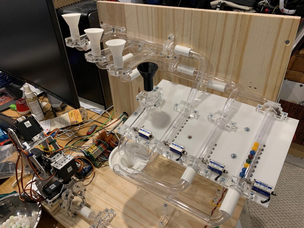
I decided to use four vertical columns to present the time, where the number of balls in a column would indicate one digit. Rather than create U-channels for the balls, I decided on transparent tubing, which is easy to form with a heat gun.
The next order of business was to direct the balls to the appropriate columns. In this case, I decided that the arm would have a separate entry point for each column. Initially, I wanted a tall device so the balls would have a spectacular descent. But the arm couldn’t reach high enough, and so I ended up with the slanted clock face you see in the photo.
The tubes are attached to a wooden frame using transparent acrylic shapes that I designed using QCAD and were cut out of 12mm acrylic sheet on a laser cutter. The connecting tubes and funnels were designed using FreeCAD and 3D printed. I have access to all these tools through my membership in a local Maker Space.
My gravitram is controlled by an Arduino Zero (bit.ly/4duRfrX) with an Adafruit 16-Channel PWM Shield (bit.ly/3SCTPmt). In addition to having more memory and a higher execution speed than an Arduino Uno, the Arduino Zero includes an embedded debugger, which I found to be essential to developing this project.
Currently, the clock works on 1-second ticks generated by the micro. My next step will be to add a real-time clock shield and use a hand-held terminal to set the time.
I started with metal balls, but the impact would dislodge balls from the “landing strip” (the part of the run where the arm grabs the ball), so I changed to plastic balls. A secondary benefit is that the plastic can be dyed, thereby increasing the visual appeal of the system.
The problem of displacement on the landing strip was not cured, so I added a pawl to feed only one ball at a time. The balls jammed in the throat of the large funnel intermittently, so I added a vibrator, which resolved the issue, albeit making a loud buzzing during the process.
The solenoids releasing the balls are activated sequentially to limit the number of balls entering the large funnel at any time.
The motion of the arm is mapped to discrete settings of the servo motors, translating to discrete points in space. The play in the joints of the arm, coupled with the accuracy and repeatability of the servo motors (magnified by the length of each arm segment), led to placement problems. I hope I have corrected these issues, but I worry that there may be future changes with age and manual handling.
You can see the unit in action on YouTube: (bit.ly/3Skh3xo).
Got a design project you’d care to share?
Contact our Editor: