Oscillation may exist under certain operating conditions but be absent under others.
by Ron Stull, Content Manager at Bel Fuse Inc.
When something doesn’t work out-of-the-box, engineers usually need to figure out if it’s really broken or if there’s something else going on.
If it was a DC-to-DC converter in that box, one of the first things to check is if the input impedance of the converter is interacting with the output impedance of the source supplying the power to the converter. Under those circumstances, the output voltage of the converter will have a significant AC component and the input voltage at the converter will also have a noticeable AC signal present.
We’re going to start by positing a constant impedance load applied to the output of the DC-to-DC converter. A DC-to-DC converter with a constant output power load draws constant power, independent of the applied voltage. In the load we set up, as the input voltage applied to the DC-to-DC converter rises, the input current falls, and vice versa. In other words, there is negative incremental resistance.
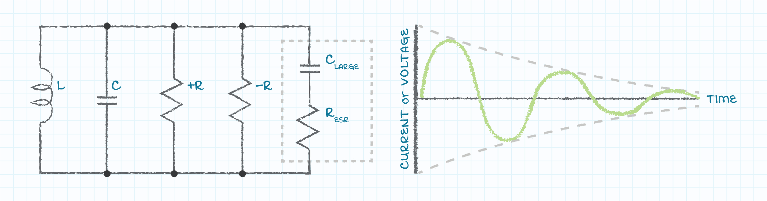
At this point, it is useful to review the behavior of a circuit that includes a capacitor and an inductor. In such a circuit, applied energy will swap between the electric field associated with the capacitor and the magnetic field associated with the inductor. The result will appear as a sinusoidal voltage across the elements and the current flowing through the elements—it will look like an oscillating circuit. The oscillation will be sustained when the negative input impedance of the DC-to-DC converter cancels the positive impedance of the associated capacitance and inductance.
Fair warning: this kind of circuit is difficult to accurately model, as oscillation will exist under certain operating conditions but be absent under others. To avoid this oscillation, it is relatively easy to add positive resistance between the output of the power source and the input of the DC-to-DC converter such that an oscillation is not sustained. There are three options:
1. Place a resistive element in series between the power source and the DC-to-DC converter.
2. Place a resistive element in shunt across the output of the power source and the input to the DC-to-DC converter.
3. AC couple a resistance into the circuit or DC block the resistance from the circuit.
The first two options end up dissipating too much power, however, so it’s the third that’s recommended. This can be accomplished by adding an electrolytic capacitor with a large capacitive value near the input pins of the DC-to-DC converter (see the figure).
The result is that the DC-to-DC converter will behave as expected. Hopefully this short guide helps other engineers. If you’d like further instructions on this or other issues, please check out the Resource Library on www.cui.com.
www.belfuse.com