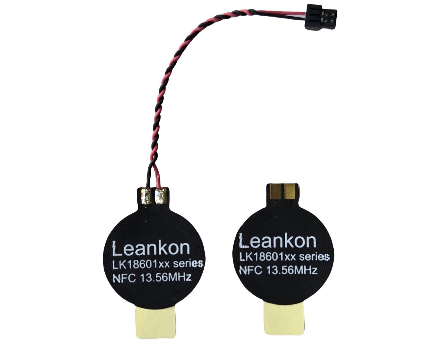
Every 13.56 MHz NFC design goes through the same sequence: select the chipset, integrate the protocol stack, and validate against certification requirements. The antenna—chosen by size from a catalog and dropped wherever the enclosure leaves room—gets far less attention. It works on the bench, but once the enclosure closes and a battery sits next to the coil, detection range collapses.
That gap between bench testing and real-world performance is rarely a chipset problem; it is an RF physics problem the antenna was never specified to solve.
Metal is the first failure mode
Battery packs, chassis panels, and shielding layers put conductive material within millimeters of the coil. At 13.56 MHz, this proximity induces eddy currents in the metal that oppose the coil’s magnetic field, detuning resonance and collapsing read range by up to 90%.
The solution is not a higher-power chipset, but inserting a high-permeability magnetic ferrite layer between the coil and metal. This channels flux around the conductor rather than into it.
The PCB is rarely where the read needs to happen
Product enclosures often place the main board 20 to 50 mm from the housing face. PCB-mounted coils cannot bridge this gap, so cable-terminated antennas must sit directly at the RF window. However, cable choice is critical: standard stranded wire increases series resistance at 13.56 MHz, severely degrading circuit Q-factor.
Multi-strand Litz wire, constructed from individually insulated strands near the copper skin depth (approx 18 µm), maintains Q-factor over wire runs exceeding 100 mm. Pair it with locking connectors—pogo pins for field-serviceable modules or ACH connectors for high-volume production—to prevent mechanical reliability issues.
Late-stage changes shouldn’t mean a respin
Layout constraints are often finalized late in development after tooling is locked. The way around this is specifying antenna lines that share identical mechanical footprints across four configurations:
Bare flexible coil.
- Flexible coil with ferrite shielding.
- Flexible coil with Litz wire termination.
- Flexible coil with both ferrite and Litz wire.
Discovering a metal-proximity issue in prototype testing then becomes a simple component swap rather than a costly PCB respin.
Eliminating validation gaps
Datasheet inductance (L) and Q-factor alone do not guarantee detection distance. To resolve validation gaps, antennas must be pre-evaluated against target controllers—such as the NXP PN7160 and ST ST25R3911B—mapping detection ranges across NFC Forum Tag Types 1 through 5.
To address these integration hurdles, Leankon has developed a comprehensive family of nine NFC antenna sizes featuring all four footprint-compatible configuration options. Evaluating free prototyping samples directly inside target enclosures during early proof-of-concept (PoC) testing further reduces redesign risk.