
Matt Reynolds, Director of Marketing Piezo & Protection Devices, TDK Electronics.
Some of the most demanding capacitor applications are in hybrid and electric vehicles (xEVs).
Capacitors are arguably the most abundantly used passive component in electronic designs. They are used in filters, amplifiers, power supplies, and as decoupling devices for most ICs. All capacitors operate off the same fundamental principle of storing charge. Where capacitors differ, however, is in the materialused to create them. The selected material will determine characteristics such as size, capacitance, cost, operating voltage, operating temperature, and usable frequencies of operation. Different types of capacitors include ceramic, tantalum, polypropylene, and PLZT (lead lanthanum zirconium titanate).
Some of the most demanding capacitor applications are in hybrid and electric vehicles (xEVs). The power delivery system in an xEV consists of the power supply (battery) and the load in which the power is being consumed. Multiple loads are often connected to additional DC rails supplied by switch- mode power supplies. The connections between these power supplies are called DC links and almost always include a capacitor. Its main job is to stabilize and smooth out the DC voltage, but it also protects the circuit from unexpected voltage spikes.
When choosing a capacitor to use in a given application, the required capacitance is a great place to start. However, additional factors that need to be considered include operating voltage, temperature robustness, and parasitics, such as equivalent series inductance (ESL) and equivalent series resistance (ESR). The ESL and ESR will determine the device’s usable frequency range and self-resonance frequency (SRF). It is important to operate within the specifications of the voltage and temperature of the component to avoid critical damage while understanding that its effective capacitance changes over both variables. Consider the plots showing how the capacitance of a typical Class II 1 μF/630 V multilayer ceramic capacitor (MLCC) will change over its operating temperature and voltage.
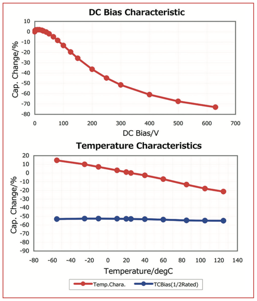
As shown in the plots, if you use the MLCC at a voltage level of half the rated voltage, it is not a 1μF capacitor anymore
but a 0.7μF part. This is a critical piece of information in many designs and—when factoring in temperature changes—it will only worsen.
While the above is true for MLCCs with Class II dielectric, PLZT-based capacitors tend to have opposite characteristic slopes. For instance, the capacitance of CeraLink capacitors from TDK, which have PLZT ceramics as their base material, increases with DC bias voltage and operating temperature. In fact, the rated capacitance of these parts occurs at or near its recommended operating voltage levels. PLZT-based capacitors also feature low ESR at higher frequencies, making them ideal as DC link capacitors and snubber capacitors in high-voltage and high- temperature applications such as power systems in modern-day xEVs. The purpose of capacitors in snubber networks and DC link connections is somewhat similar. They help reduce the effects of parasitic inductance caused by long routes or wire runs. Since the inductance resists change in current, an abrupt switch can cause a large voltage overshoot and potentially damage the switching device. In these instances, the capacitor helps to provide the instantaneous current required when a switch occurs.
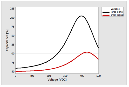
also a 2220 series, this one with an operating voltage (VOP) of 400V. The red line shows the capacitance of the device with a very low AC ripple applied; the black line shows the part with a significant ripple of approximately ±20V. Source: TDK
Similarly, PLZT-based capacitors are ideal for use in high-temperature applications. Though polypropylene capacitors can also provide the energy density required, their performance quickly deteriorates as the temperature rises.
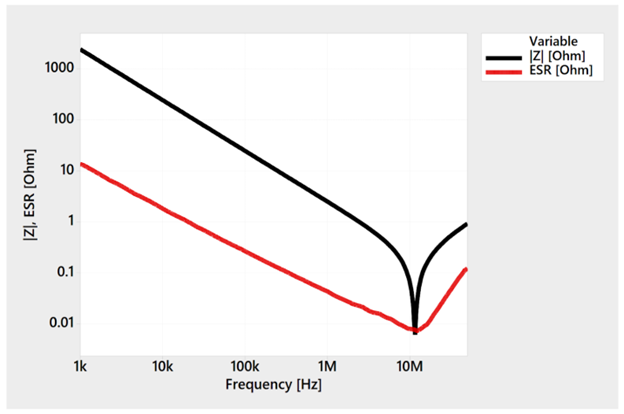
PLZT-based capacitors are also well-suited for high-switching frequency applications, for instance, to reduce the overall capacitance needed. The components have an ESR that decreases with an increase in temperature to achieve its minimum ESR at higher temperatures. This characteristic allows the devices to achieve a very high ripple current rating and minimum ESR in real-world applications.
To achieve the required capacitance, capacitors are generally connected in parallel. For example, using a 100nF capacitor from another vendor at a voltage of 400V will only yield an effective capacitance of57nF. Therefore, to achieve the effective 100nF of capacitance, multiple devices would have to be used. On the other hand, if an 85nF CeraLink device is used, the effective capacitance at 400V is approximately 250nF. This is double what is required, and approximately four to five Class II ceramic chips of the same size would have to be used in parallel to achieve the same capacitance of the single PLZT component.
CeraLink capacitors from TDK are available with voltage ratings from 500V to 900V and in several different package styles, including SMD 2220, solder pin, low profile with J-style and L-style terminations, and flex assembly packages for multi-chip assemblies. Their high-temperature range, low losses, and high-power handling make them ideally suited for high- voltage xEV applications. They can help simplify a design, offer robustness and reliability that cannot befound with other capacitors, and reduce BOM costs.